A Bar Magnet Is Broken in Half Each Half Is Broken in Half Again Etc
![]()
20.one Magnetic Fields, Field Lines, and Force
Resource ID: DNG1q49J@6
Grade Range: PreK - 12
Learning Objectives
Learning Objectives
By the stop of this section, you will be able to exercise the following:
- Summarize properties of magnets and describe how some nonmagnetic materials can become magnetized
- Describe and interpret drawings of magnetic fields effectually permanent magnets and current-carrying wires
- Calculate the magnitude and direction of magnetic force in a magnetic field and the force on a electric current-carrying wire in a magnetic field
| Curie temperature | domain | electromagnet |
| electromagnetism | ferromagnetic | magnetic dipole |
| magnetic field | magnetic pole | magnetized |
| northward pole | permanent magnet | right-hand dominion |
| solenoid | south pole |
Magnets and Magnetization
Magnets and Magnetization
People have been aware of magnets and magnetism for thousands of years. The primeval records date back to ancient times, specially in the region of Asia Pocket-size called Magnesia—the proper name of this region is the source of words like magnet. Magnetic rocks found in Magnesia, which is at present part of western Turkey, stimulated interest during ancient times. When humans first discovered magnetic rocks, they likely found that certain parts of these rocks attracted bits of iron or other magnetic rocks more strongly than other parts. These areas are called the poles of a magnet. A magnetic pole is the part of a magnet that exerts the strongest force on other magnets or magnetic textile, such as iron. For example, the poles of the bar magnet shown in Figure 20.2 are where the paper clips are concentrated.

Effigy twenty.2 A bar magnet with paper clips attracted to the two poles.
If a bar magnet is suspended and so that information technology rotates freely, one pole of the magnet will always turn toward the northward, with the opposite pole facing south. This discovery led to the compass, which is simply a pocket-sized, elongated magnet mounted so that it can rotate freely. An example of a compass is shown Effigy twenty.3. The pole of the magnet that orients northward is called the north pole, and the opposite pole of the magnet is called the south pole.

Figure 20.3 A compass is an elongated magnet mounted in a device that allows the magnet to rotate freely.
The discovery that 1 particular pole of a magnet orients northward, whereas the other pole orients southward allowed people to identify the north and south poles of whatever magnet. It was then noticed that the northward poles of two dissimilar magnets repel each other, and likewise for the southward poles. Conversely, the due north pole of one magnet attracts the due south pole of other magnets. This situation is coordinating to that of electrical charge, where similar charges repel and different charges attract. In magnets, we simply replace charge with pole: Like poles repel and unlike poles attract. This is summarized in Figure 20.iv, which shows how the force between magnets depends on their relative orientation.

Figure 20.4 Depending on their relative orientation, magnet poles volition either concenter each other or repel each other.
Consider again the fact that the pole of a magnet that orients northward is chosen the north pole of the magnet. If unlike poles concenter, then the magnetic pole of Earth that is close to the geographic N Pole must exist a magnetic south pole! Likewise, the magnetic pole of Earth that is close to the geographic Due south Pole must be a magnetic north pole. This situation is depicted in Figure twenty.5, in which Earth is represented as containing a giant internal bar magnet with its magnetic s pole at the geographic North Pole and vice versa. If we were to somehow append a giant bar magnet in infinite nearly Earth, then the northward pole of the infinite magnet would be attracted to the south pole of Earth's internal magnet. This is in essence what happens with a compass needle: Its magnetic due north pole is attracted to the magnet south pole of Earth'south internal magnet.

Figure twenty.5 Earth can exist thought of as containing a giant magnet running through its core. The magnetic south pole of Earth'southward magnet is at the geographic Northward Pole, so the north pole of magnets is attracted to the Due north Pole, which is how the n pole of magnets got their name. Likewise, the south pole of magnets is attracted to the geographic South Pole of World.
What happens if yous cut a bar magnet in half? Do you obtain one magnet with two due south poles and 1 magnet with two north poles? The reply is no: Each half of the bar magnet has a north pole and a south pole. You tin can even keep cutting each piece of the bar magnet in one-half, and you will ever obtain a new, smaller magnet with ii opposite poles. As shown in Effigy twenty.6, you can continue this procedure downwardly to the atomic scale, and yous will find that even the smallest particles that conduct as magnets have 2 opposite poles. In fact, no experiment has ever found any object with a single magnetic pole, from the smallest subatomic particle such equally electrons to the largest objects in the universe such as stars. Because magnets e'er have 2 poles, they are referred to as magnetic dipoles—di means 2. Below, we volition come across that magnetic dipoles have properties that are analogous to electrical dipoles.

Figure 20.half-dozen All magnets have 2 opposite poles, from the smallest, such every bit subatomic particles, to the largest, such equally stars.
Watch Physics
Introduction to Magnetism
This video provides an interesting introduction to magnetism and discusses, in particular, how electrons effectually their atoms contribute to the magnetic effects that we observe.
Grasp Check
Toward which magnetic pole of Earth is the north pole of a compass needle attracted?
- The northward pole of a compass needle is attracted to the north magnetic pole of World, which is located near the geographic North Pole of Earth.
- The north pole of a compass needle is attracted to the south magnetic pole of Globe, which is located near the geographic Due north Pole of Globe.
- The north pole of a compass needle is attracted to the n magnetic pole of Earth, which is located near the geographic South Pole of Globe.
- The north pole of a compass needle is attracted to the s magnetic pole of Earth, which is located near the geographic Due south Pole of Globe.
Only certain materials, such as iron, cobalt, nickel, and gadolinium, exhibit strong magnetic effects. Such materials are called ferromagnetic, after the Latin word ferrum for iron. Other materials showroom weak magnetic effects, which are detectable just with sensitive instruments. Not only do ferromagnetic materials reply strongly to magnets—the style iron is attracted to magnets—merely they can also be magnetized themselves—that is, they can be induced to be magnetic or fabricated into permanent magnets (Effigy xx.vii). A permanent magnet is only a textile that retains its magnetic behavior for a long time, even when exposed to demagnetizing influences.

Figure twenty.seven An unmagnetized piece of iron is placed between two magnets, heated, and then cooled, or just tapped when cold. The iron becomes a permanent magnet with the poles aligned as shown: Its southward pole is adjacent to the n pole of the original magnet, and its north pole is next to the south pole of the original magnet. Note that attractive forces are created between the primal magnet and the outer magnets.
When a magnet is brought virtually a previously unmagnetized ferromagnetic material, it causes local magnetization of the material with dissimilar poles closest, as in the right side of Figure 20.vii. This causes an bonny force, which is why unmagnetized iron is attracted to a magnet.
What happens on a microscopic scale is illustrated in Figure 7(a). Regions within the material called domains act similar small bar magnets. Inside domains, the magnetic poles of private atoms are aligned. Each atom acts like a tiny bar magnet. Domains are small and randomly oriented in an unmagnetized ferromagnetic object. In response to an external magnetic field, the domains may grow to millimeter size, adjustment themselves, as shown in Figure vii(b). This induced magnetization tin can be made permanent if the material is heated and then cooled, or just tapped in the presence of other magnets.

Figure 20.8 (a) An unmagnetized piece of iron—or other ferromagnetic cloth—has randomly oriented domains. (b) When magnetized by an external magnet, the domains show greater alignment, and some grow at the expense of others. Individual atoms are aligned within domains; each atom acts similar a tiny bar magnet.
Conversely, a permanent magnet can exist demagnetized by hard blows or by heating it in the absence of another magnet. Increased thermal motion at higher temperature can disrupt and randomize the orientation and size of the domains. There is a well-defined temperature for ferromagnetic materials, which is chosen the Curie temperature, above which they cannot be magnetized. The Curie temperature for atomic number 26 is i,043 K (770), which is well above room temperature. There are several elements and alloys that have Curie temperatures much lower than room temperature and are ferromagnetic merely below those temperatures.
Snap Lab
Refrigerator Magnets
We know that like magnetic poles repel and unlike poles concenter. Run into if you tin can show this for two fridge magnets. Volition the magnets stick if you turn them over? Why practice they stick to the fridge door anyway? What can you say about the magnetic properties of the refrigerator door near the magnet? Practice fridge magnets stick to metal or plastic spoons? Do they stick to all types of metallic?
Grasp Check
Yous take one magnet with the north and s poles labeled. How can you use this magnet to identify the northward and southward poles of other magnets?
- If the north pole of a known magnet is repelled past a pole of an unknown magnet on bringing them closer, that pole of unknown magnet is its north pole; otherwise, information technology is its south pole.
- If the due north pole of known magnet is attracted to a pole of an unknown magnet on bringing them closer, that pole of unknown magnet is its due north pole; otherwise, information technology is its due south pole.
Magnetic Fields
Magnetic Fields
We have thus seen that forces can exist applied between magnets and between magnets and ferromagnetic materials without any contact betwixt the objects. This is reminiscent of electric forces, which also deed over distances. Electric forces are described using the concept of the electric field, which is a forcefulness field around electric charges that describes the forcefulness on any other charge placed in the field. Likewise, a magnet creates a magnetic field around information technology that describes the forcefulness exerted on other magnets placed in the field. Equally with electric fields, the pictorial representation of magnetic field lines is very useful for visualizing the force and direction of the magnetic field.
Every bit shown in Figure 20.9, the direction of magnetic field lines is defined to be the direction in which the north pole of a compass needle points. If you place a compass near the north pole of a magnet, the northward pole of the compass needle will exist repelled and point abroad from the magnet. Thus, the magnetic field lines indicate away from the due north pole of a magnet and toward its south pole.

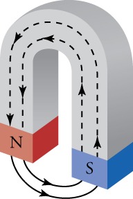
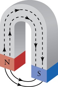
Figure xx.9 The black lines stand for the magnetic field lines of a bar magnet. The field lines indicate in the direction that the north pole of a small compass would betoken, as shown at left. Magnetic field lines never end, so the field lines actually penetrate the magnet to course complete loops, every bit shown at correct.
Magnetic field lines can be mapped out using a pocket-sized compass. The compass is moved from point to point effectually a magnet, and at each signal, a curt line is drawn in the direction of the needle, as shown in Figure twenty.11. Joining the lines together then reveals the path of the magnetic field line. Some other fashion to visualize magnetic field lines is to sprinkle iron filings effectually a magnet. The filings will orient themselves forth the magnetic field lines, forming a pattern such as that shown on the right in Figure 20.11.
Virtual Physics
Using a Compass to Map Out the Magnetic Field
This simulation presents you with a bar magnet and a small compass. Begin by dragging the compass around the bar magnet to come across in which direction the magnetic field points. Note that the strength of the magnetic field is represented by the effulgence of the magnetic field icons in the grid pattern around the magnet. Use the magnetic field meter to check the field strength at several points around the bar magnet. You can likewise flip the polarity of the magnet, or place Earth on the image to see how the compass orients itself.
Grasp Check
With the slider at the superlative right of the simulation window, gear up the magnetic field strength to 100 percent . Now use the magnetic field meter to answer the following question: Most the magnet, where is the magnetic field strongest and where is it weakest? Don't forget to check inside the bar magnet.
- The magnetic field is strongest at the centre and weakest between the ii poles but outside the bar magnet. The magnetic field lines are densest at the center and to the lowest degree dense between the 2 poles just outside the bar magnet.
- The magnetic field is strongest at the center and weakest between the two poles just outside the bar magnet. The magnetic field lines are least dense at the heart and densest between the ii poles just outside the bar magnet.
- The magnetic field is weakest at the centre and strongest betwixt the two poles simply exterior the bar magnet. The magnetic field lines are densest at the eye and least dense betwixt the two poles just outside the bar magnet.
- The magnetic field is weakest at the center and strongest between the two poles just outside the bar magnet and the magnetic field lines are least dense at the center and densest between the two poles just exterior the bar magnet.

Effigy 20.11 Magnetic field lines tin can be drawn by moving a small compass from betoken to signal around a magnet. At each point, draw a short line in the direction of the compass needle. Joining the points together reveals the path of the magnetic field lines. Another manner to visualize magnetic field lines is to sprinkle iron filings effectually a magnet, as shown at right.
When ii magnets are brought close together, the magnetic field lines are perturbed, just as happens for electric field lines when two electric charges are brought together. Bringing ii due north poles together—or 2 south poles—will crusade a repulsion, and the magnetic field lines volition bend away from each other. This is shown in Figure xx.12, which shows the magnetic field lines created past the two closely separated north poles of a bar magnet. When opposite poles of two magnets are brought together, the magnetic field lines join together and become denser between the poles. This situation is shown in Figure 20.12.

Effigy 20.12 (a) When two north poles are approached together, the magnetic field lines repel each other and the 2 magnets experience a repulsive force. The same occurs if 2 south poles are approached together. (b) If opposite poles are approached together, the magnetic field lines become denser between the poles and the magnets experience an attractive force.
Like the electric field, the magnetic field is stronger where the lines are denser. Thus, between the two northward poles in Figure 20.12, the magnetic field is very weak considering the density of the magnetic field is about zero. A compass placed at that point would essentially spin freely if we ignore Earth'due south magnetic field. Conversely, the magnetic field lines between the north and south poles in Effigy twenty.12 are very dense, indicating that the magnetic field is very strong in this region. A compass placed here would quickly marshal with the magnetic field and point toward the s pole on the correct.
Misconception Alert
The density of the magnetic field lines in Figure 20.12 indicates the magnitude of the forcefulness that would be applied to a minor exam magnet placed in this field. The density does not indicate the strength betwixt the 2 magnets that create the field. The magnitude of the force between the two magnets is the same in both cases in Effigy 20.12. This can exist understood by imagining that you identify one of the magnets in the field of the other magnet. This situation is symmetrical: The magnetic fields await the aforementioned—other than direction—for both situations shown in Figure twenty.12. Because the magnets are of equal strength, they perturb the magnetic field of the reverse magnet, which is why the magnetic field must be probed by a modest magnetic such as, a compass.
Notation that magnets are not the merely things that make magnetic fields. Early in the nineteenth century, people discovered that electrical currents cause magnetic effects. The first significant observation was by the Danish scientist Hans Christian Oersted (1777–1851), who found that a compass needle was deflected by a electric current-conveying wire. This was the commencement significant evidence that the motility of electric charges had any connectedness with magnets. An electromagnet is a device that uses electric current to make a magnetic field. These temporarily induced magnets are called electromagnets. Electromagnets are employed for everything from a wrecking yard crane that lifts scrapped cars to decision-making the axle of a 90-km-circumference particle accelerator to the magnets in medical-imaging machines (encounter Figure twenty.13).

Figure 20.thirteen Instrument for magnetic resonance imaging (MRI). The device uses a cylindrical-coil electromagnet to produce for the main magnetic field. The patient goes into the tunnel on the gurney. (credit: Bill McChesney, Flickr)
The magnetic field created by an electric current in a long directly wire is shown in Figure 20.xiv. The magnetic field lines class concentric circles effectually the wire. The management of the magnetic field can be determined using the right-hand rule. This rule shows upward in several places in the study of electricity and magnetism. Practical to a direct current-carrying wire, the right-hand dominion says that, with your right thumb pointed in the direction of the current, the magnetic field will be in the management in which your right fingers curl, as shown in Figure xx.14. If the wire is very long compared to the distance r from the wire, the forcefulness B of the magnetic field is given by
20.1
where I is the current in the wire in amperes. The SI unit for magnetic field is the tesla (T). The symbol —read "mu-nil"—is a abiding chosen the "permeability of complimentary infinite" and is given by
xx.2

Figure twenty.14 This image shows how to use the correct-hand rule to determine the management of the magnetic field created past current flowing through a directly wire. Point your correct thumb in the management of the current, and the magnetic field will be in the direction in which your fingers ringlet.
Sentry Physics
Magnetic Field Due to an Electric Current
This video describes the magnetic field created by a straight electric current-carrying wire. It goes over the right-hand rule to determine the direction of the magnetic field, and presents and discusses the formula for the strength of the magnetic field due to a straight current-carrying wire.
Grasp Check
A long direct wire is placed on a table top and electrical electric current flows through the wire from right to left. If yous look at the wire terminate-on from the left end, does the magnetic field go clockwise or counterclockwise?
- By pointing your right-hand thumb in the direction reverse of current, the right-hand fingers volition curl counterclockwise, then the magnetic field will exist in the counterclockwise management.
- Past pointing your right-hand thumb in the management opposite of current, the right-manus fingers will whorl clockwise, so the magnetic field will be in the clockwise direction.
- By pointing your right-hand thumb in the management of current, the correct-hand fingers will curl counterclockwise, so the magnetic field will exist in the counterclockwise management.
- By pointing your correct-hand thumb in the direction of current, the right-hand fingers will curl clockwise, so the magnetic field will be in the clockwise management.
Now imagine winding a wire around a cylinder with the cylinder then removed. The upshot is a wire ringlet, as shown in Figure twenty.fifteen. This is called a solenoid. To detect the direction of the magnetic field produced by a solenoid, apply the right-hand rule to several points on the scroll. You should exist able to convince yourself that, inside the coil, the magnetic field points from left to right. In fact, some other application of the right-hand rule is to curl your correct-paw fingers effectually the whorl in the direction in which the current flows. Your correct pollex and so points in the direction of the magnetic field within the coil: left to right in this case.

Figure 20.15 A wire curl with current running through as shown produces a magnetic field in the management of the scarlet pointer.
Each loop of wire contributes to the magnetic field inside the solenoid. Because the magnetic field lines must form closed loops, the field lines shut the loop outside the solenoid. The magnetic field lines are much denser inside the solenoid than exterior the solenoid. The resulting magnetic field looks very much like that of a bar magnet, as shown in Figure 20.16. The magnetic field strength deep inside a solenoid is
20.iii
where North is the number of wire loops in the solenoid and is the length of the solenoid.

Figure 20.16 Iron filings show the magnetic field pattern around (a) a solenoid and (b) a bar magnet. The fields patterns are very like, specially near the ends of the solenoid and bar magnet.
Virtual Physics
Electromagnets

Utilise this simulation to visualize the magnetic field made from a solenoid. Exist sure to click on the tab that says Electromagnet. You can bulldoze Air-conditioning or DC current through the solenoid by choosing the advisable current source. Utilise the field meter to measure the force of the magnetic field so modify the number of loops in the solenoid to see how this affects the magnetic field strength.
Grasp Cheque
Choose the battery as electric current source and fix the number of wire loops to 4. With a nonzero electric current going through the solenoid, measure out the magnetic field force at a point. At present subtract the number of wire loops to two. How does the magnetic field strength modify at the bespeak you chose?
- There will be no modify in current when number of loops reduces from four to ii.
- The current decreases to half of its initial value when number of loops reduces from 4 to two.
- The electric current increases to twice of its initial value when number of loops reduces from four to two.
- The electric current increases to four times of its initial value when number of loops reduces from iv to two.
Magnetic Force
Magnetic Force
If a moving electric charge, that is electric current, produces a magnetic field that tin exert a force on some other magnet, and then the reverse should be truthful by Newton'due south 3rd police force. In other words, a charge moving through the magnetic field produced by another object should experience a force—and this is exactly what nosotros observe. As a physical example, consider Figure 20.xviii, which shows a charge q moving with velocity through a magnetic field between the poles of a permanent magnet. The magnitude F of the force experienced past this charge is
where is the bending between the velocity of the charge and the magnetic field.
The direction of the force may be plant past using another version of the right-hand rule: Outset, we join the tails of the velocity vector and a magnetic field vector, as shown in step 1 of Figure twenty.18. We then gyre our right fingers from to , every bit indicated in step (2) of Figure xx.18. The direction in which the right thumb points is the direction of the force. For the charge in Figure 20.18, we observe that the force is directed into the page.
Note that the factor in the equation ways that zero force is applied on a accuse that moves parallel to a magnetic field because and . The maximum force a charge tin can experience is when it moves perpendicular to the magnetic field, because and

Figure twenty.18 (a) An electron moves through a uniform magnetic field. (b) Using the right-manus rule, the forcefulness on the electron is found to be directed into the page.
Links To Physics
Magnetohydrodynamic Drive
In Tom Clancy'due south Cold State of war novel "The Chase for Reddish October," the Soviet Union congenital a submarine (see Figure 20.xix) with a magnetohydrodynamic drive that was then silent it could not be detected by surface ships. The only believable purpose to build such a submarine was to requite the Soviet Matrimony first-strike capability, because this submarine could sneak close to the coast of the Us and burn its ballistic missiles, destroying fundamental military and government installations to prevent an American counterattack.

Figure twenty.nineteen A Typhoon-grade Russian ballistic-missile submarine on which the fictional submarine Red Oct was based.
A magnetohydrodynamic drive is supposed to exist silent considering it has no moving parts. Instead, information technology uses the forcefulness experienced by charged particles that motility in a magnetic field. The bones idea behind such a drive is depicted in Figure twenty.twenty. Table salt water flows through a channel that runs from the front to the dorsum of the submarine. A magnetic field is applied horizontally beyond the channel, and a voltage is applied across the electrodes on the top and bottom of the channel to strength a down electric current through the water. The charge carriers are the positive sodium ions and the negative chlorine ions of salt. Using the right-hand rule, the strength on the charge carriers is found to be toward the rear of the vessel. The accelerated charges collide with h2o molecules and transfer their momentum, creating a jet of water that is propelled out the rear of the channel. Past Newton'southward third police, the vessel experiences a force of equal magnitude, but in the opposite direction.

Figure xx.twenty A schematic drawing of a magnetohydrodynamic drive showing the water aqueduct, the electric current direction, the magnetic field direction, and the resulting strength.
Fortunately for all involved, information technology turns out that such a propulsion organization is non very practical. Some dorsum-of-the-envelope calculations evidence that, to power a submarine, either extraordinarily loftier magnetic fields or extraordinarily high electric currents would exist required to obtain a reasonable thrust. In addition, prototypes of magnetohydrodynamic drives prove that they are annihilation just silent. Electrolysis caused by running a current through table salt water creates bubbles of hydrogen and oxygen, which makes this propulsion system quite noisy. The organisation also leaves a trail of chloride ions and metal chlorides that tin can easily be detected to locate the submarine. Finally, the chloride ions are extremely reactive and very apace corrode metal parts, such as the electrode or the water aqueduct itself. Thus, the Red October remains in the realm of fiction, but the physics involved is quite real.
Grasp Check
If the magnetic field is downwards, in what direction must the current catamenia to obtain rearward-pointing force?
- The electric current must period vertically from up to down when viewed from the rear of the boat.
- The current must flow vertically from down to up when viewed from the rear of the boat.
- The electric current must menstruum horizontally from left to right when viewed from the rear of the boat.
- The current must menstruum horizontally from correct to left when viewed from the rear of the boat.
Instead of a single charge moving through a magnetic field, consider at present a steady current I moving through a direct wire. If nosotros place this wire in a uniform magnetic field, equally shown in Figure 20.21, what is the force on the wire or, more precisely, on the electrons in the wire? An electrical electric current involves charges that move. If the charges q move a distance in a time t, so their speed is Inserting this into the equation gives
20.5
The factor q/t in this equation is nada more than the current in the wire. Thus, using , we obtain
twenty.6
This equation gives the force on a straight current-carrying wire of length in a magnetic field of force B. The angle is the angle between the current vector and the magnetic field vector. Annotation that is the length of wire that is in the magnetic field and for which as shown in Figure 20.21.
The direction of the force is determined in the aforementioned style as for a unmarried charge. Whorl your right fingers from the vector for I to the vector for B, and your right thumb will point in the direction of the force on the wire. For the wire shown in Figure 20.21, the force is directed into the page.

Effigy xx.21 A straight wire carrying current I in a magnetic field B. The force exerted on the wire is directed into the page. The length is the length of the wire that is in the magnetic field.
Throughout this section, you may have noticed the symmetries between magnetic effects and electric effects. These effects all fall nether the umbrella of electromagnetism, which is the report of electric and magnetic phenomena. Nosotros have seen that electric charges produce electrical fields, and moving electrical charges produce magnetic fields. A magnetic dipole produces a magnetic field, and, as nosotros will run across in the next department, moving magnetic dipoles produce an electric field. Thus, electricity and magnetism are ii intimately related and symmetric phenomena.
Worked Example
Trajectory of Electron in Magnetic Field
A proton enters a region of abiding magnetic field, as shown in Figure 20.22. The magnetic field is coming out of the folio. If the electron is moving at and the magnetic field strength is two.0 T, what is the magnitude and direction of the force on the proton?

Effigy 20.22 A proton enters a region of uniform magnetic field. The magnetic field is coming out of the page—the circles with dots represent vector pointer heads coming out of the page.
STRATEGY
Use the equation to find the magnitude of the force on the proton. The bending between the magnetic field vectors and the velocity vector of the proton is The direction of the strength may be constitute by using the right-manus rule.
Solution
The charge of the proton is . Inbound this value and the given velocity and magnetic field forcefulness into the equation gives
xx.7
To find the direction of the force, first bring together the velocity vector finish to end with the magnetic field vector, as shown in Figure xx.23. Now place your correct hand and then that your fingers point in the direction of the velocity and curl them upward toward the magnetic field vector. The force is in the management in which your pollex points. In this case, the force is down in the airplane of the paper in the -management, equally shown in Figure 20.23.

Figure 20.23 The velocity vector and a magnetic field vector from Figure twenty.22 are placed stop to end. A correct hand is shown with the fingers curling up from the velocity vector toward the magnetic field vector. The thumb points in the direction of the resulting force, which is the -management in this case.
Thus, combining the magnitude and the direction, we find that the force on the proton is
Give-and-take
This seems like a very small force. However, the proton has a mass of , so its acceleration is , or about ten thousand billion times the dispatch due to gravity!
Nosotros found that the proton'southward initial acceleration as it enters the magnetic field is down in the plane of the page. Find that, as the proton accelerates, its velocity remains perpendicular to the magnetic field, then the magnitude of the force does not change. In addition, considering of the right-hand dominion, the direction of the force remains perpendicular to the velocity. This strength is naught more than than a centripetal force: It has a constant magnitude and is always perpendicular to the velocity. Thus, the magnitude of the velocity does not alter, and the proton executes circular motion. The radius of this circumvolve may be establish by using the kinematics human relationship.
20.8
The path of the proton in the magnetic field is shown in Figure 20.24.

Figure 20.24 When traveling perpendicular to a abiding magnetic field, a charged particle will execute round motion, equally shown hither for a proton.
Worked Example
Wire with Current in Magnetic Field
At present suppose we run a wire through the uniform magnetic field from the previous example, equally shown. If the wire carries a current of 1.0 A in the -direction, and the region with magnetic field is 4.0 cm long, what is the strength on the wire?

STRATEGY
Employ equation to find the magnitude of the force on the wire. The length of the wire inside the magnetic field is iv.0 cm, and the angle between the current direction and the magnetic field direction is 90°. To find the direction of the force, employ the right-hand dominion as explained but after the equation
Solution
Insert the given values into equation to find the magnitude of the force
20.9
To discover the direction of the force, begin by placing the electric current vector end to cease with a vector for the magnetic field. The result is as shown in the effigy in the previous Worked Case with replaced by . Roll your right-hand fingers from to and your right pollex points downwards the page, once again as shown in the effigy in the previous Worked Instance. Thus, the direction of the forcefulness is in the -management. The consummate strength is thus .
Word
The direction of the force is the same as the initial direction of the force was in the previous case for a proton. However, because the current in a wire is confined to a wire, the direction in which the charges move does not alter. Instead, the entire wire accelerates in the -management. The force on a current-carrying wire in a magnetic field is the ground of all electrical motors, equally we will encounter in the upcoming sections.
Practise Problems
Practice Problems
What is the magnitude of the strength on an electron moving at one.0 × 106 m/s perpendicular to a ane.0-T magnetic field?
- 0.8 × ten–13 N
- 1.six × 10–14 Due north
- 0.8 × 10–fourteen N
- 1.half dozen × 10–xiii Northward
A straight 10 cm wire carries 0.40 A and is oriented perpendicular to a magnetic field. If the force on the wire is 0.022 N , what is the magnitude of the magnetic field?
- one.10 × 10–2 T
- 0.55 × 10–ii T
- 1.10 T
- 0.55 T
Bank check Your Understanding
Cheque Your Agreement
Do one
If 2 magnets repel each other, what tin you conclude about their relative orientation?
- Either the southward pole of magnet ane is closer to the n pole of magnet 2 or the due north pole of magnet one is closer to the southward pole of magnet 2.
- Either the s poles of both the magnet one and magnet 2 are closer to each other or the north poles of both the magnet 1 and magnet ii are closer to each other.
Exercise 2
Describe methods to demagnetize a ferromagnet.
- by cooling, heating, or submerging in h2o
- by heating, hammering, and spinning information technology in external magnetic field
- by hammering, heating, and rubbing with fabric
- by cooling, submerging in h2o, or rubbing with cloth
Exercise iii
What is a magnetic field?
- The directional lines present within and exterior the magnetic material that point the magnitude and management of the magnetic forcefulness.
- The directional lines nowadays inside and outside the magnetic material that betoken the magnitude of the magnetic force.
- The directional lines present inside the magnetic material that indicate the magnitude and the direction of the magnetic strength.
- The directional lines present outside the magnetic fabric that indicate the magnitude and the direction of the magnetic force.
Exercise iv
Depict the magnetic field lines for a horseshoe-shaped magnet. Be certain to label the due north and south poles of the magnet.


Source: https://www.texasgateway.org/resource/201-magnetic-fields-field-lines-and-force
0 Response to "A Bar Magnet Is Broken in Half Each Half Is Broken in Half Again Etc"
Post a Comment